OIML BULLETIN - VOLUME LXV - NUMBER 4 - October 2024
t e c h n i q u e
Linking the readings of an automatic level gauge to the calibration table of a tank before it is put into operation
Samoilenko Oleksandr, Zaiets Volodymyr, Akolzin Ivan
State Enterprise “State Research and Production Center of Standardization, Metrology, Certification and Consumers’ Rights Protection” (SE “UKRMETRTESTSTANDART”)
4, Metrologichna str., 03143 Kyiv, Ukraine
Abstract
The problem of linking the readings of an automatic level gauge (ALG) installed on a tank to its calibration table is quite acute and well known to tank calibration laboratories, engineers who install ALGs, and tank operations staff. If the problem is not solved, then the consequences can be very significant systematic biases during the measurements of the volume and mass of liquids by tanks.
The problem arises because it is at the border between the two procedures for tank calibration and ALG installation. It is not described in the instructions and the guides, so not all specialists pay enough attention to it. A calibration laboratory may make a gross error in linking the tank calibration table to its reference points when calibrating a tank by the manual or electro-optical distance-ranging method. If this is not detected and corrected during the ALG installation, the consequences will be acutely felt by those who operate the tanks during fiscal and/or custody liquid operations.
The following are precautions should be taken when calibrating tanks and installing ALGs so that the error in linking the readings of an automatic level gauge to calibration table of tank is minimal.
1. Introduction
The calibration of tanks by means of the electro-optical distance-ranging (geodetic) measuring method using laser scanners is unequalled in terms of speed, accuracy and cost [1 – 17]. But this method will only be effective enough if we have mathematically strict and objective methods for linking the readings of automatic level gauges (ALG) to the calibration table of a tank before they are put into operation (problem of the ALG readings linking to the calibration table).
OIML R 71 [18] specifies that the maximum permissible uncertainty for the capacity of tanks calculated according to the GUM [19] for k = 2, shall be equal to:
- 0.2 % of the indicated volume for vertical cylindrical tanks;
- 0.3 % of the indicated volume for horizontal or tilted cylindrical tanks;
- 0.5 % of the indicated volume for other tanks.
The use of the electro-optical distance-ranging (geodetic) measuring method allows the accuracy of the capacity determination to be significantly improved. The experimental expanded uncertainty of the tank’s incremental capacity is:
- 0.05 % – 0.1 % for vertical tilted and non-tilted cylindrical tanks;
- 0.1 % – 0.2 % for horizontal and spherical tanks;
- 0.1 % – 0.3 % for arbitrary geometrical tanks shape.
According to OIML R 85 [20], in the field of legal metrology, it is recommended to use ALGs with the maximum permissible error of liquid level measurement in the range ± 1 mm during testing and verification in the laboratory. According to [20] the maximum permissible error (MPE) of the liquid level measurement using the ALG should be ± 4 mm during operation on the tank.
According to ISO 4266 [21 – 23] an even smaller MPE is established: “The total error of the ALG in a fiscal/custody conditions transfer application should not be affected by more than ± 3 mm due to installation, due to variation of operating conditions, and due to variation of physical and electrical properties of the liquid and/or vapour, provided these conditions are within the limits specified by the ALG manufacturer”. However, in this standard, the linking problem is not even mentioned among the reasons that can cause deterioration in the accuracy of liquid volume and mass measurements using the tank and ALG.
This MPE includes the measurement error component associated with linking the readings of an automatic level gauge to the calibration table. Considering other components of the MPE, the error (expanded uncertainty) of linking among them should not exceed 1–2 mm for small-sized tanks,
1–2.5 mm for medium-sized tanks, and 1–3 mm for large-sized tanks.
The above means that there can be a systematic bias of the zero of the calibration table up or down relative to the point from which the liquid level will be measured. This can lead to a significant deterioration of the specified accuracy. The problem of the ALG readings linking to the calibration table for horizontal, spherical and arbitrary shaped tanks can increase the liquid volume measurement extended uncertainty to 0.3 % – 1 % with use of the tank and ALG.
In the standards [1 – 7] and a number of publications [8 – 10], no attention is paid to this important problem at all, but only to the measurement and calculation of the volume of the tanks during their calibration. In the standards [11 – 13] developed by the authors of this publication, some attention is paid to linking the reference point of the total station or scanner to the tank’s dipping datum point, but this is not enough. In the authors’ publications [14 – 17] attention is paid to complex cases of linking. For example, in [14] for horizontal tanks there is a solution for the case when the tank’s dipping datum point cannot be identified. In [14], for vertical tanks, a scan sweep is given, where the weight of the dipping tape measure installed on the dipping datum point of the tank can clearly be recognized. In [16] a carefully developed linking of the calibration table of the spherical tank to the ALG readings is presented, when there is no dipping datum point, and the linking is carried out through the ALG flange.
In publication [8], the processing of the results of the scanning of the spherical tank is given, but unlike [16], the method of calculating the calibration table and the method of linking it to the ALG readings are not given.
The advantage of the scanner given in [9, 10] is the ability to scan through a small hole in the lid of the tank, but its measurement is not linked to the tank’s dipping datum point in any way. This scanner cannot scan the bottom of the tank. This is clearly visible in the figure in [10].
Thus, the purpose of this publication is to improve the accuracy of static volume measurements of liquids using tanks by improving the accuracy of linking the tank calibration table with ALG readings.
Much of what is discussed in this publication is reflected in one way or another in the Working Draft (WD) Guide OIML G ...-1:2025 Fixed storage and transportable tanks. Calibration using electro-optical distance-ranging method. Part 1: Requirements for automatic measurements. This document compiles the tanks calibration best practices using the electro-optical distance-ranging measuring method. All aspects of linking the tank calibration table with the ALG readings is also included in this document.
Therefore, we invite all interested parties, and above all members of OIML TC 8/SC 1 Static volume and mass measurement, to become involved in improving the WD of this publication.
2. Influence linking the readings of an automatic level gauge to the calibration table on liquid volume measurement uncertainty
The influence linking the readings of an automatic level gauge to the calibration table on liquid volume measurement uncertainty is different for different type of tanks. For smaller tanks, the effect of the same biases on the error of the volume measurements is greater.
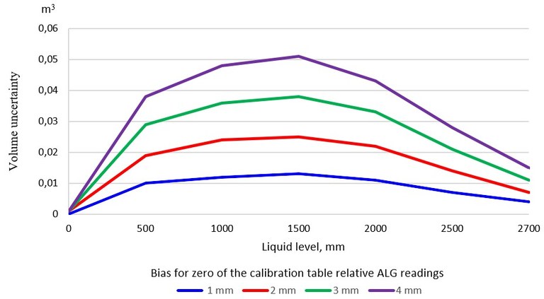
Figure 1: Influence linking the readings of an ALG to the calibration table on liquid volume measurement uncertainty for a 25 m3 horizontal cylindrical tank
From Figure 1, it can be concluded that for horizontal cylindrical tanks with a capacity of approximately 25 m3, it is desirable that the bias for zero of the calibration table relative to the ALG readings does not exceed 2 mm. Then, the error in the measurement of the volume of liquid does not exceed 25 L in the middle of the tank.
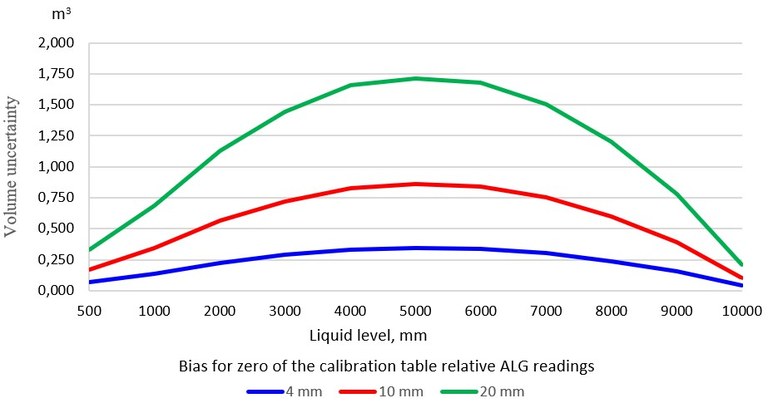
Figure 2: Influence linking the readings of an ALG to the calibration table on liquid volume measurement uncertainty for a 600 m3 spherical tank
From Figure 2, it can be concluded that for spherical tanks with a capacity of approximately 600 m3, the bias for zero of the calibration table relative to the ALG readings of nearly 4 mm is satisfactory (error in the measurement of the volume of liquefied gas 0.35 m3). But, if the dimensions of the spherical tank are not determined from measurements, but taken from the drawings, then an error of 20 mm in the geometric dimensions of the tank leads to a significant error in the measurement of the volume of liquefied gas of more than 1.75 m3 in the middle of the tank.
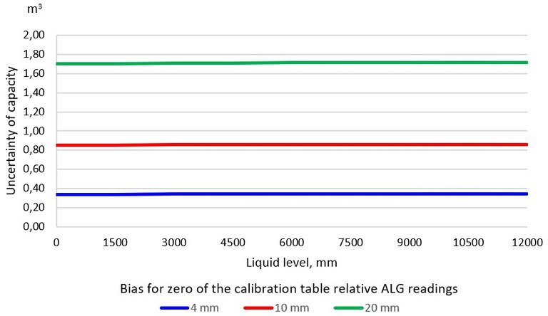
Figure 3: Influence linking the readings of an ALG to the calibration table on liquid volume measurement uncertainty for a 1000 m3 vertical cylindrical tank
From Figures 1 and 2 we can see that linking the readings of an ALG to the calibration table significantly affects the accuracy of each daily liquid volume measurement by horizontal cylindrical and spherical tanks. There is no such effect for vertical cylindrical tanks. That is, the linking error does not affect the accuracy of the daily liquid volume measurement of vertical cylindrical tanks. The effect is only on the measurement of the total volume of liquid in the tank during its first filling. In addition, the deformation of the bottom of a vertical cylindrical tank can be larger than the linking error, so a linking error of 4 mm when the scanner measurement is performed from the outside of the tank is quite acceptable.
Figure 4 plots the relative error in the liquid volume measurement that can be caused by the 4 mm error of linking the tank’s calibration table to the ALG readings versus the percentage of tank fill. The blue curve is for a 25 m3 horizontal cylindrical tank (hor), the red curve is for a 600 m3 spherical tank (sph), and the green curve is for a 1000 m3 vertical cylindrical tank (ver).
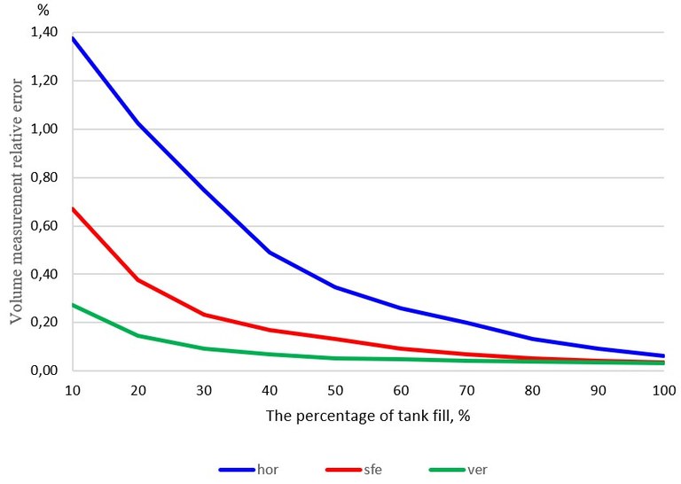
Figure 4: Volume measurement relative error that can be caused by the error linking the readings of an ALG to the calibration table
Figure 4 confirms that the error of 4 mm for a 25 m3 horizontal cylindrical tank is too large, for a 600 m3 spherical tank is the maximum allowable error, and for a 1000 m3 vertical cylindrical tank is an acceptable error.
3. Tanks classification by operation purpose and linking place
From the point of view of solving the problem of linking the tank calibration table with the ALG readings, the tanks should be divided into two large groups.
The first group (Figure 5) are tanks that are operated under atmospheric pressure or a small excess pressure (not more than 0.1 MPa) and are used to store oil and petroleum products. The second group are tanks that are operated under pressure up to 1.8 MPa and are used to store liquefied petroleum gas. The difference between these groups is that the first group can perform manual measurements of the liquid level with a dipping tape, which meet the requirements of OIML R 35 [24], and the second group does not. Therefore, the first ones have a hatch for measuring with a dipping tape and a place for mounting ALG, and the second only for mounting ALG.
Obtaining high-accuracy measurements of the volume and mass of liquids using the tanks calibrated electro-optical distance-ranging method measurements by laser scanners is possible only if these measurements are performed in the same height system as the liquid level measurement. That is, the height measurement of all points by scanners and the measurement of the liquid level by the ALG must be performed relative to the same reference points. Methods of linking measurements made by scanners and measurements made by the ALG through reference points solve the problem of linking the calibration table with the ALG readings.
For tanks of the first group, such reference points are the dipping datum point and the upper reference point of the tank and the horizontal plane of the flange on which the ALG will be mounted (Figure 5), and for tanks of the second group only the horizontal plane of the ALG flange. In fact the horizontal plane of the ALG flange is the ALG upper reference point. Sometimes a dipping datum point ALG can be set. For tanks of the first group, the zero of the tank calibration table is aligned with the dipping datum point of the tank. For tanks of the second group, the zero of the calibration table can be aligned with any horizontal plane, including the lower ALG reference point, but the height of this plane must be precisely known relative to the ALG flange.
During the calibration of the tanks of the first group, it is necessary to ensure reliable linking of the reference point of the scanner to the dipping datum point of the tank. Linking the reference point of the scanner to the ALG flange on the tanks of the first group will enable independent control of the linking using a dipping tape.
During the calibration of the tanks of the second group, it is necessary to ensure reliable linking of the reference point of the scanner to the ALG flange. An alternative can be only the volumetric linking method described below. Of course, it is possible to determine the geometric dimensions of the tanks, especially spherical and horizontal cylindrical ones, necessary for the installation of ALG, with the help of working drawings of the tanks. But it should be borne in mind that manufacturing errors of such a large structure (for example, the diameter of a spherical tank with a capacity of 1000 m3 is 12.3 m) can be from 10 to 50 mm without harming their operational properties, but unacceptable for accurate linking.
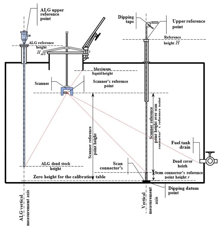
Figure 5: Scanner reference point height relative dipping datum point for internal tanks calibration
4. Brief description of tank calibration using the electro-optical distance-ranging method
The final result of measurements using the electro-optical distance-ranging method is the millions of 3D coordinate points on all the surfaces from the inside or outside of the tanks, which can be reached by the laser beam directed by the scanner. The standard deviation of the coordinate measurements is 1–3 mm. The systematic error component of the remote measurements should not exceed 0.5 mm for small tanks, 1 mm for medium tanks, and 2 mm for large ones.
All point coordinates x, y, z measured from one measurement point (measurement station) are called a scan. The origin (zero place) of the coordinate system for each scan is the reference point of the scanner, which is the point of intersection of its horizontal and vertical axes of rotation and the optical axis of the laser beam.
Direct linking of the scan coordinate system to the dipping datum point is carried out by internal measurements, and to the ALG flange by external ones. For the external calibration of the tanks of the first group to the coordinate system of one or more scans linking the upper reference point of the tank and, if necessary, the ALG flange. For the internal calibration of the tanks of the second group, the ALG flange is indirectly linked to the coordinate system of one or more scans.
It is important that the axis z of each scan coincides with a plumb line, that is, it is oriented in the same direction as the direction of the level measurements. When recalculating the coordinates of each scan (if there are several scans, because for internal measurements there can be only one scan), it is necessary to align the origin (zero) of the scanner coordinate system with the dipping datum point of the tank for tanks operating at atmospheric pressure (first group) to a single coordinate system X, Y, h of the tank. The coordinate h is the height of any point in the tank relative to the dipping datum point or ALG flange. For tanks that operate under excess pressure (second group), the height h reference is made to the flange on which the ALG will be installed or is already installed. Linking to the ALG flange for tanks operating at atmospheric pressure is a mandatory procedure if it is not possible to link to a dipping datum point.
If it is impossible to make linking using the geometric method, then linking can be done using the volumetric method according to section 5.
5. Classification of ALGs by the method of measuring the height of the liquid level and linking tanks calibration tables to their readings
ALGs can also be divided into groups. The first includes those that measure the height of the level from a certain reference point, for example, servo-driven ALGs. They are in automatic mode, lower the float on a thin wire, and, with high accuracy, fix the moment of touching both the surface of the liquid and the ALG dipping datum point. Thus, the servo-driven ALG measures the level from the ALG dipping datum point to the surface of the liquid. Dipping tape is a non-automatic measuring device according to OIML R 35 [24], which also measures the height of the liquid level relative to the dipping datum point.
For this ALG group, it is sufficient to link the tank calibration table to the ALG dipping datum point. No additional procedures are required. If the calibration table is linking to the tank’s dipping datum point, then for such an ALG, the usual linking procedure is performed using dipping tape.
That is, if the calibration table of the tank is linked to the ALG dipping datum point of this group, which can be recognized on the scan made in the tank, then the ALG linking process has already been done during the creation of the calibration table. The same can be said about the calibration table, if the level is measured with a dipping tape and the calibration table is linked to the tank’s dipping datum point.
The second group of ALGs includes those that measure the difference between two values of the height of the level, for example, magnetostrictive. The probe of this ALG in the form of a thin tube is mounted vertically so that its end does not touch the bottom or wall of the tank. The zero position of the scale of such an ALG is not linked to the end of the tube. In order for the float on the tube to float, the height of the liquid level must reach approximately 30–60 mm. That is, it is impossible to measure the height of the liquid level with such an ALG relative to the reference point on the tank, with which the zero of the calibration table is aligned.
The second group of ALGs measures the difference between some arbitrary liquid level and all others. The readings of such ALGs must be linked to the calibration table. The liquid level must be measured with another ALG or with a dipping tape relative to the reference point with which the zero of the calibration table is aligned. The measured level must be entered into the ALG settings along with the calibration table.
The third group of ALGs includes those that measure the height of unfilled space (ullage). For example, these are radar ALGs that measure the distance from the flange on which they are installed to the surface of the liquid (ullage). For the third ALG group, the reference height of the flange for the installation of the ALG must be defined (ALG reference height).
The ALG reference height is the distance from the horizontal plane that passes through the dipping datum point of the tank to the horizontal plane that passes through the ALG flange. During the filling of the tank, which belongs to the tanks of the first group, the liquid level is measured with a dipping tape and the height of the unfilled space is measured using ALG. The ALG reference height is calculated by the formula:
![]()
where
hi is the liquid level measured with a dipping tape equal to the height of the liquid surface relative dipping datum point;
Ci is the ullage height measured by an automatic level gauge.
The height of the unfilled space for this linking method can be measured by the ALG from an arbitrary point, not from the flange on which the ALG is mounted.
The reference height HALGi is entered into the ALG to calculate the liquid level hi from the measured height of the unfilled space Ci. If possible, it is recommended to repeat such measurements at several liquid levels and enter the averaged value into the ALG.
For the second group of tanks, a dipping tape measurement cannot be performed. For this group, the reference height HALG can be determined only during the calibration of the tanks. For spherical tanks, the procedure for measurements and calculations during calibration, as well as the procedure for linking the calibration table with ALG readings with mathematically rigorous uncertainty evaluation, is described in detail by the authors of this publication in [16]. The ALG reference height HALG of the spherical tank is determined indirectly during least square method approximation by the sphere of the coordinate measurements results on the surface of the tank. The ALG reference height HALG of the spherical tank is the vertical distance from the ALG flange to the bottom point of the approximating sphere.
With minor additions, this procedure can be applied to horizontal cylindrical tanks of the second group.
We would like to emphasize that there is no alternative to the method described in [16] for tanks of the second group, that is, for those operated under excess pressure.
At the same time, if the ALG measures the height of the unfilled space (ullage), then it must be calibrated so that its measurement zero coincides with its reference surface, which is installed on the corresponding flange of the tank. The thickness of the gasket between the flange surface and the ALG reference surface must be added to the ALG reference height.
The method described is also suitable for tanks of the first group, if measurements with a dipping tape are not possible for some reason. For tanks of the first group, this method provides independent control if measurements with a dipping tape are possible.
6. Linking the calibration table to the ALG readings using the volumetric method
Linking the calibration table obtained from the results of the tank scanning with the ALG readings using the volumetric method is used when it is impossible to determine the height of the reference point of the scanner above the dipping datum point of the tank or ALG. Even if such linking is performed during tank scanning, the volumetric method can be an effective method of controlling and clarifying such linking. According to our estimates and experience, this method is the most accurate.
This method can be applied to any types of tanks that are operated at atmospheric pressure (the first group) before their operation, both with the possibility of measuring the liquid level with a dipping tape, and with the possibility of measuring only the level with the ALG. This method can be applied to tanks of the second group before they are put into operation, if the filling of water and its removal from the tank is technically possible and economically justified.
This method is recommended to be used to refine the linking even when the height of the scanner reference point above the dipping datum point of the tank has been determined, for example, it is effective for small horizontal tanks.
Pour one or more known doses of liquid (e.g. fuel) into the tank through a volume measurement standard (volume measure) or meter according to ISO 4269 [25]. These doses should not be large. For example, for a tank with a nominal capacity of 10 to 50 m3, it can be several doses poured into a volume measurement standard with a capacity of 0.05, 0.1 or 0.2 m3 and uncertainty of capacity 0.05 % (first column of Table 1). For accurate and reliable linking, it is necessary to pour from 3 to 5 doses of liquid. After each draining, the level must be measured with a dipping tape, dipstick and/or ALG (third column of Table 1).
Table 1 Measurement and processing bias of calibration table

For a vertical tank, it is necessary to pour several doses through the meter to a height of the liquid level from 50 to 500 mm. This will also allow the bottom to be deformed under the weight of the poured liquid.
In the calibration table (it should be drawn after 1 mm), select the liquid levels that correspond to the doses poured into the tank (the second column of table 1) and record them in the fourth column of Table 1. These values are subtracted from the values of the levels measured with a dipping tape and/or ALG and written in the fifth column of Table 1. Large deviations from the average of the differences should be discarded and a new average value calculated. The average between these differences gives the bias by which the calibration table must be shifted. To all the point heights in the file of point coordinates on the surface of the tank, the value of the resulting bias is added, taking into account its sign. The software used must have the appropriate functionality. The calibration table is recalculated and checked against column 3 of Table 1.
The ALG readings are set taking into account the value of the averaged bias of the calibration table.
If the ALG measures the height of the unfilled space Ci (ullage), then formula (1) is used to calculate HALGi. But, in formula (1) hi is the interpolated liquid level (not measured with a dipping tape) by the measured and poured into the tank liquid volume (fourth column of Table 1). The average value from HALGi is entered into the ALG. The calibration table of the tank does not change.
7. Linking the calibration table to the ALG readings using the indirect geometrical method
To carry out internal measurements and other work in the tank the tank hatch cover can be dismounted together with the guide pipe where the upper reference point is located. At the same time the task of the direct identification (localization) of the dipping datum point may be complicated or impossible (location of dipping datum point is unknown). The indirect geometrical method of linking the scanner measurements to the dipping datum point is to solve this task.
On one side of a special rod a scanner is mounted and on the other side a laser level (crossliner) (Figure 6). The distance d from the scanner reference point to the rod end is precisely known from the metrological measurements with an uncertainty better 0.5 mm. The tank is scanned by a scanner mounted on a rod in the upside-down position. After tank scanning, the first reading r1 is carried out by a level laser beam using a tape scale.
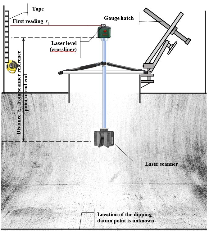
Figure 6 Scanning of the horizontal cylindrical underground tank through its hatch
After the tank hatch and the guide pipe are mounted on what is the upper reference point at the gauge hatch, the laser level is mounted on it and the second reading r2 is performed by a level laser beam using the tape scale (Figure 7). The reference height H is measured by the dipping tape.
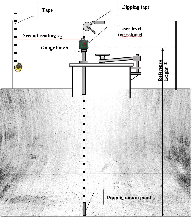
Figure 7 Laser level at the gauge hatch of the horizontal cylindrical underground tank
The height h0 of the scanner reference point regarding the tank dipping datum point, when the location of the dipping datum point is unknown, is calculated by the formula:
![]()
where cD is the additive constant of the scanner distance range on the results of its calibration.
The signs r1 and r2 in formula (8) are given for the case when the zero of the tape is on top (Figures 6 and 7). If the zero of the tape is on the bottom, then the signs should be reversed to the opposite.
The height h is used for calculating the points’ height on the tank surface in the 3D reference coordinate system. These 3D coordinates is use for calculating the tank calibration table.
8. Conclusions
- The error of linking the tanks calibration table to the ALG readings has a significant impact on the error of measuring the volume and mass of liquids using tanks. This error can be greater than the errors of the calibration tables obtained by the electro-optical distance-ranging method of measurement by laser scanners and other error components.
- There is no international document that would unambiguously and mathematically accurately describe the procedures for linking the tank calibration table to the ALG readings. An OIML publication, consisting of a series of several Guides (OIML G) entitled Fixed storage and transportable tanks. Calibration using electro-optical distance-ranging method is being developed. They will cover automated measurement methods using scanners and manual measurement methods using total stations. The methods of measuring and calculating the capacity of tanks described in the Guides will involve solving the problem of linking the tank calibration table to the ALG readings.
9. References
- EN ISO 8311:2013 Refrigerated hydrocarbon and non-petroleum based liquefied gaseous fuels – Calibration of membrane tanks and independent prismatic tanks in ships – manual and internal electro-optical distance-ranging methods. Switzerland: ISO; 2013. p. 39
- ISO 7507-2:2022 Petroleum and liquid petroleum products – Calibration of vertical cylindrical tanks – Part 2: Optical-reference-line method or electro-optical distance-ranging method. Switzerland: ISO; 2022. p. 28
- ISO 7507-4:2010 Petroleum and liquid petroleum products – Calibration of vertical cylindrical tanks – Part 4: Internal electro-optical distance-ranging method. Switzerland: ISO; 2010. p. 20
- ISO 7507-5:2000 Petroleum and liquid petroleum products – Calibration of vertical cylindrical tanks – Part 5: External electro-optical distance-ranging method. Switzerland: ISO; 2000. p. 11
- [5] ISO 12917-2:2002 Petroleum and liquid petroleum products – Calibration of horizontal cylindrical tanks – Part 2: Internal electro-optical distance-ranging method. Switzerland: ISO; 2002. p. 14
- API Standard. Manual of Petroleum Measurement Standards. Chapter 2 – Tank Calibration. Section 2D – Calibration of Upright Cylindrical Tanks Using the Internal Electro-optical Distance Ranging Method. USA Standard. American Petroleum Institute; 2003. p. 11.
- API Standard 2552 (R2018). Method for measurement and calibration of spheres and spheroids. USA Standard. American Petroleum Institute; 1965. p. 17.
- Wang Jintao, Tong Lin, Ma Xinyuand Zheng He The Non-contact Precision Measurement for Spherical Metrology Tank Journal of Physics: Conference Series, Volume 1065, Issue 4 Citation Wang Jintao et al 2018 Phys.: Conf. Ser. 1065 042029 Published under license by IOP Publishing Ltd
- 3D LASER Startitaliana. http://www.startitaliana.com/areatest/prodotti_hscroll_laser.php#info
- 3D Laser Tank Calibration System. Tokheim ProGauge. https://www.pshglobalgroup.com/product/3d-laser-tank-calibration-system/
- GOST 8.655-2016 The reservoirs for fluid gas steel spherical. Methods of the verification (calibration) by geometrical method with the use of the geodetic instruments (DSTU 7474 IDT). Minsk: Euro-Asian council for standardization, metrology and certification; 2016. p. 75
- GOST 8.656-2016 The vertical measurement reservoirs. Methods of the verification (calibration) by geometrical method with the use of the geodetic instruments (DSTU 7473 IDT). Minsk: Euro-Asian council for standardization, metrology and certification; 2016. p. 112
- GOST 8.659-2016 The reservoirs steel cylindrical horizontal. Methods of the verification (calibration) by geometrical method with the use of the geodetic instruments (DSTU 7475 IDT). Minsk: Euro-Asian council for standardization, metrology and certification; 2016. p. 108
- Samoilenko O., Zaets V. October 2021 Calibration of Tanks and Ships’ Tanks for Storage and Transportation of Liquids by Laser Scanning. Applied Aspects of Modern Metrology. DOI: 10.5772/intechopen.100565
- Samoylenko, V. Zaets Interlaboratory comparisons of tank capacity calculated by laboratories’ own software – key stage of their proficiency testing OIML bulletin, – Paris.: Volume LIX, Number 4, October 2018. pp. 5-11
- Samoylenko, V. Zaets Evaluation of the uncertainties of the geometrical parameters and capacity of spherical tanks – Paris.: OIML Bulletin, Volume LVII, Number 4, October 2016. pp. 10-16
- Samoylenko, V. Zaets Evaluation by least square method of geometrical parameters and capacity of all tank tapes by the results of laser scanning – Paris.: OIML Bulletin, Volume LVI, Number 3, July 2015. pp. 14-21
- OIML R 71:2008 Fixed storage tanks. General requirements. Paris – France: Bureau International de Métrologie Légale; 2008. Available from: https://www.oiml.org. p. 22
- OIML G 1:1995 Guide to the expression of uncertainty in measurement (GUM). Paris – France: Bureau International de Métrologie Légale; 2008. Available from: https://www.oiml.org.
- OIML R 85-1&2:2008 Automatic level gauges for measuring the level of liquid in stationary storage tanks. Part 1: Metrological and technical requirements. Part 2: Metrological control and tests. Paris – France: Bureau International de Métrologie Légale; 2008. Available from: https://www.oiml.org. p. 49
- ISO 4266-1:2002 Petroleum and liquid petroleum products – Measurement of level and temperature in storage tanks by automatic methods — Part 1: Measurement of level in atmospheric tanks. Switzerland: ISO; 2002. p. 18
- ISO 4266-2:2002 Petroleum and liquid petroleum products – Measurement of level and temperature in storage tanks by automatic methods — Part 2: Measurement of level in marine vessels. Switzerland: ISO; 2002. p. 11
- ISO 4266-3:2002 Petroleum and liquid petroleum products – Measurement of level and temperature in storage tanks by automatic methods — Part 3: Measurement of level in pressurized storage tanks (non-refrigerated). Switzerland: ISO; 2002. p. 15
- OIML R 35-1:2007 Material measures of length for general use Part 1: Metrological and technical requirements. Paris – France: Bureau International de Métrologie Légale; 2008. Available from: https://www.oiml.org. p. 36
- ISO 4269:2001 Petroleum and liquid petroleum products – Tank calibration by liquid measurement – Incremental method using volumetric method. Switzerland: ISO; 2001. p. 26
<< previous | contents | next >>


